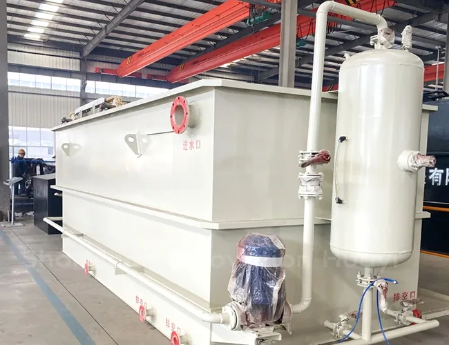
Where the working principle begins, and where it is usually lost
The dissolved air flotation working principle fits in one sentence: air is dissolved into a pressurised stream of water, released into the tank as a crowd of micro-bubbles, and those bubbles attach to oil droplets and lift them to the surface.
- How much oil is left in the water leaving the tank
- How much water is carried away with the recovered oil
- Whether the unit keeps delivering both, day after day
Those three results are settled by three questions of construction: how fine the bubbles are by the time they meet the oil, how evenly they are spread through the tank, and what happens to the oil once it is floating.
Two units can share a footprint and a tank volume and still behave differently on the same wastewater, because those three answers come from the geometry inside the unit rather than from the size of it. The design this note walks through is one such geometry — the dissolved air flotation oil remover covered by Chinese utility model CN206486308U — and it reads as an answer to two specific complaints about the units already on the market.
The first complaint is about how the oil leaves. With a mechanical scraper, or through an overflow outlet set into the side of the tank, the floating layer reaches the outlet carrying a good deal of water with it: the oil recovered is dilute, and water that could have stayed in the plant leaves with it. The second is about how the bubbles are made. A conventional saturation vessel discharges its dissolved-air water straight into the flotation tank, the water and air inside that vessel do not mix evenly, gas solubility is hard to hold, and the bubbles arrive in the tank unevenly distributed and at a size the design does not really control. Neither complaint is answered by a larger tank. The rest of this note therefore stays with the geometry of one design, so that every question attaches to a part you can point at in a drawing.
Following one drop of water through the machine
How does dissolved air flotation work, in the order the water travels? The sequence is fixed, and each stage has one job to do.
- A stream of clarified water is pressurised and saturated with air, so the air goes into solution rather than into bubbles.
- The pressurised stream is released into the tank, and the drop in pressure lets the dissolved air come out as micro-bubbles.
- The bubbles meet oil droplets in a contact zone and attach to the droplet surface.
- Each droplet-and-bubble floc rises, because its combined density is well below that of water.
- The oil layer is drawn off the surface as a concentrate, and clarified water leaves from lower down the tank.
That sequence is common to every dissolved air flotation unit on the market. What differs is the hardware that carries each stage out, and it is worth checking against a drawing.
The machine at a glance: a cone top, a cone bottom, no scraper
The unit in this walkthrough is a vertical tank with a conical top and a conical bottom and no scraper mechanism anywhere in it. Fig. 1 is the dissolved air flotation diagram that goes with it, redrawn from the patent drawing, with the callouts numbered exactly as in that drawing.
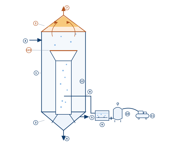
- 1 tank body · 2 conical top · 3 conical bottom · 4 inlet · 5 outlet · 6 drain (lowest point) · 7 oil outlet (apex).
- 8 dissolved-air water inlet · 9 release box (square steel tank holding the releasers) · 10 saturation vessel (pressure tank with a gauge) · 11 mobile air compressor · 12 mixing chamber.
- 122 sieve plate (annular slots, 20 mm). The numbering follows the patent drawing, so the figure can be read side by side with the original.
Read it in the order the water travels and three things stand out. The raw wastewater inlet is high on the tank wall, so the flow starts by moving down the outside of the central cylinder. The dissolved-air water arrives at the bottom of that cylinder instead of into the bulk of the tank. And the two outlets sit at opposite ends of the design: oil at the apex, treated water near the base. A DAF oil water separator is usually compared on tank volume, footprint and a quoted removal rate, and none of those three tells you what leaves the top.
Detail 1: a conical top instead of a scraper
The roof of the tank is a cone, and the oil outlet sits at its highest point. Oil is lighter than water, so once the flocs rise the oil rides up the cone surface and is squeezed toward the apex: the higher it climbs, the smaller the cross-section it has to pass through, and the thicker the oil layer becomes. What leaves at the apex is concentrated oil with very little water in it.
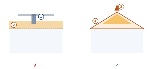
- 1 mechanical scraper — a moving part that drags the floating layer off, oil and water together. 2 the floating oil layer before removal.
- 3 apex discharge — the only outlet the oil needs. 4 oil self-concentrating as it climbs the cone.
- ✗ left: watery sludge and a moving part to maintain. ✓ right: dry oil and zero moving parts.
This is where the disposal bill is decided. A mechanical scraper drags a band of water off the surface along with the oil, and that water travels with the oil to whoever takes it away. A conical top with an apex outlet carries no scraper and produces a drier concentrate, and it is also one motor, one chain and one gearbox fewer to maintain over the life of the unit.
The scraper and the cone face the same floating layer. The gap in water content comes from three places:
- Skimming folds water back in. A blade travelling along the surface stirs the blanket and pulls the water below up into the oil. What leaves is always a strip of freshly agitated oil-and-water mixture.
- A layer left alone drains itself. The water between the flocs is heavier than the oil and, undisturbed, percolates back down through the gaps under gravity. The thicker the blanket grows and the longer it sits, the drier its top becomes.
- The narrowing section squeezes it once more. Buoyancy lifts the oil into a tighter and tighter space and the layer compacts. What finally overflows at the apex is the oil that has sat highest and drained longest. A scraper works on its travel cycle and takes thin layers that have not had time to drain; the apex outlet is self-regulating and releases nothing until the layer has built up to it.
The trade-off is worth naming before you choose a design on this detail alone: an apex outlet depends on the oil layer building up and staying mobile, so a wastewater whose oil is emulsified — or a peak load that arrives faster than the flocs can rise — will not behave the way the cone is designed for. Geometry fixes the top of the tank, not the chemistry inside it.
Detail 2: a tangential swirl chamber where the bubbles finish forming
The second detail decides the quality of the bubbles, and with them the second half of the dissolved air flotation oil removal problem. Fine, uniform bubbles attach to oil droplets. Coarse and uneven ones either miss the droplets or break up the flocs they have already formed. If the dissolved-air stream is discharged straight into a tank full of wastewater, it is sheared apart and its bubbles coalesce into large useless ones before they have fully formed.
This design answers with a coaxial cylinder in the middle of the tank, working as an isolation bay. Dissolved-air water enters at the bottom of that cylinder tangentially, skimming along the inner wall rather than shooting straight in. The water spins into a vortex, the shear releases the dissolved air as a crowd of fine, uniform bubbles, and only then are the bubbles let out to meet the wastewater.
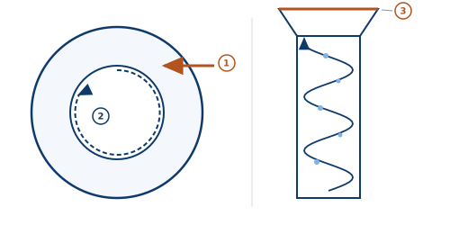
- 1 dissolved-air water entering tangentially — it skims the chamber wall instead of jetting straight in.
- 2 the vortex: bubbles finish forming while spiralling inside the chamber.
- 3 the sieve plate above the outlet. Left panel is the top view; right panel is the side view.
In one sentence: a straight jet scatters the bubbles, while a tangential inlet lets them spin and mature inside the chamber first. The patent states the same logic in its own terms — the tangential arrangement lets the dissolved air be fully released, and it keeps the raw wastewater from contacting the dissolved-air water too early.
Detail 3: a sieve plate and a flared outlet
The third detail is the easiest of the three to miss, because it belongs to the outlet of the mixing chamber rather than to the tank itself.
- A sieve plate covers the chamber outlet, with annular slots 20 mm wide in the embodiment described in the patent. The swirling bubble stream has to pass through those rings, which combs it into an evenly distributed curtain instead of a few concentrated jets.
- Above the plate, the outlet widens into an inverted frustum like a trumpet. The bubble curtain fans out there and meets the incoming oily wastewater head on, which is where attachment happens, before the flocs rise into the conical roof.
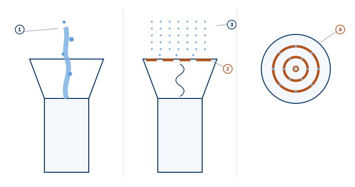
- 1 The concentrated jet without the plate — the bubbles crowd into one channel and shoot straight up.
- 2 The sieve plate — set across the inverted-frustum opening; the swirling bubble stream must pass through its slots.
- 3 The even bubble curtain — distribution is combed uniform after the slots.
- 4 The annular slots (top view) — concentric rings, 20 mm wide in the patent embodiment, the ring count set as flotation requires.
None of the three details is exotic on its own. The shape of the outlet, the plate above it and their arrangement are all visible in a drawing, and together they are the difference between an even curtain of bubbles and one concentrated jet in a tank.
Which figures to carry into a comparison, and which to leave out
Most of the dissolved air flotation design effort that decides the result sits in the saturator, the recycle rate and the contact zone, and none of that is visible in a tank photograph or a layout drawing.
Two figures are usually quoted first: tank volume and a removal rate, and neither travels well. A removal rate belongs to a particular wastewater, temperature and oil load, so the same unit quoted against a different stream is a different number. Tank volume, for its part, is closer to a footprint figure until the contact zone and the saturator behind it are specified.
The only dimension this walkthrough takes from the oil remover patent is the 20 mm annular slot, and it comes from the embodiment section of that document. Bubble size, recycle ratio and air-to-solids ratio are not derived here from the tank geometry, because they follow from the wastewater rather than from the design. The saturation figures quoted in the next section are the exception, and they come from the specification of the companion patent for the dissolved-air system: they describe what that system is built to do rather than what any one stream will return. Read any figure of that kind as a starting method rather than as a specification, and take the confirmed number from the manufacturer for your wastewater stream.
How This Design Compares to Conventional DAF Systems
Three arrangements are worth setting side by side: the conventional saturation vessel discharging straight into the flotation tank, the scraper-type rectangular flotation basin, and the design walked through above. The differences land in two places — where and how the bubbles are made, and where the floating oil leaves the tank and how much water it takes with it.
| Aspect | Conventional saturator-only DAF | Rectangular DAF with scraper | This patented design |
|---|---|---|---|
| Air dissolution and release | Water and air are pumped into a saturation vessel under pressure and the dissolved-air water leaves through its outlet straight into the flotation tank. | The same saturation vessel, with the release point inside the basin and usually a separate contact zone ahead of it. | Pre-release in a dedicated box: the dissolved-air water passes releasers in a release box and enters the mixing chamber tangentially, instead of being released straight into the basin. |
| Bubble control | Water and air mix unevenly inside the vessel, gas solubility is difficult to control, and the bubbles spread unevenly and are not uniform in size. | Bubbles form where the recycled dissolved-air water is released; the levers are the release device and the recycle ratio. | Tangential swirl + sieve plate: bubbles finish forming in the swirl at an even size, and the plate combs them into a uniform curtain while keeping raw water from meeting the dissolved-air water too early. |
| How the oil is removed | A scraper skims the floating layer, or an outlet in the tank wall draws it off. | A chain-and-flight scraper drags the floating layer along the basin to a sludge hopper or an end weir. | Self-concentrating cone top: no scraper — oil is squeezed up the cone and overflows at the apex. |
| Water carried out with the oil | A scraper or a side-wall outlet takes the floating layer off with a good deal of water in it, so the oil is dilute. | The same: the scraper removes a band of oil and water together. | Gravity drainage + a narrowing section: only the oil that has drained longest reaches the apex, so the water content is minimal. |
| Moving parts | Pumps and an air compressor on the saturation side, plus whatever mechanism clears the floating layer. | A drive, a chain, flights and a gearbox, all of them in contact with the process water or the oil layer. | No moving parts above the water: no motor, chain or gearbox to maintain. |
| Structure and footprint | A basin with a saturation package beside it. | A long rectangular basin whose length has to accommodate the scraper run. | Vertical, small footprint: height does the work, not floor area. |
Set the three arrangements side by side and the advantage of this design sits in one place: control of the bubble. The bubbles form inside an isolated chamber, in a vortex, and are combed through a sieve plate before they are released — and the same plate keeps the raw wastewater from meeting the dissolved-air water too early, which is what stops the bubble population from being damaged before it has finished forming. On the oil side the cone does the concentrating, and no moving part touches the water surface. What that buys is a drier concentrate, less water leaving with the oil, and one fewer maintenance line item than a scraper.
Common mistakes
- Comparing on tank volume or footprint alone. Two units with the same outline can produce very different volumes of oily sludge for disposal, and the difference is invisible on the layout drawing.
- Assuming that one oil-removal mechanism is as good as another. A scraper, an overflow slot and an apex outlet do different things to the water that leaves with the oil, and the difference arrives on the disposal invoice.
- Buying on a quoted oil removal rate. The percentage belongs to a wastewater and to the test that produced it, and asking which stream it was measured on is more informative than the number itself.
- Never asking how the bubbles are generated and distributed. Bubbles that coalesce before they reach the oil do the same work as coarse ones, and the drawing is where that shows.
- Counting motors late. Anything that moves across the water surface is a maintenance line item, and a design with no surface scraper has one fewer of them.
Self-check before you compare suppliers
- Where does the oil leave the tank, and what drives it there? Ask for the drawing of the oil outlet. A DAF oil water separator that depends on a scraper will show one; a self-concentrating geometry will not.
- How are the bubbles generated, distributed and protected while they form? Ask to see the dissolved air flotation diagram of the contact zone, not only the outline drawing of the tank.
- How many moving parts touch the process water or the oil layer? Each of them is a maintenance line item over the life of the unit, and each is a place a drive can fail.
- Which stream was the quoted removal rate measured on, and what was measured — oil, grease, or suspended solids?
- Are the outlet arrangement, the saturator duty and the contact-zone geometry stated for your wastewater, or copied from a general table?
Three questions, then, and a drawing behind each answer. The design described here is covered by utility model CN206486308U, filed on 27 February 2017 and public on Google Patents — one of the first eight patents in the portfolio, all of them first-authored by the same inventor. The figures above are redrawn from the patent drawing, and the figures quoted in this note are taken from the two patent specifications: the 20 mm annular slot from the embodiment of the oil remover, and the saturation data from the companion dissolved-air system. What the same questions return for your own stream — the outlet arrangement, the saturator duty and the contact-zone geometry in the unit quoted to you — is confirmed with the manufacturer for your wastewater stream rather than assumed from this note.