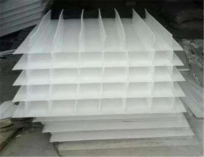
One tank, two loads
A settling tank receives two things at once. It receives a flow, which is a hydraulic load, and it receives a mass of suspended solids, which is a solids load. Treatments that deal with the first are described by a hydraulic loading rate; those that deal with the second are described by a solids loading rate. A tank has to be adequate for both, and they are not the same calculation.
The hydraulic measure of a settling tank is its surface loading rate: the flow passed through the tank divided by the plan area of the tank, expressed in cubic metres per square metre per day, or in gallons per minute per square foot in the other common convention. The same quantity is also called the overflow rate, and where a plant is described in terms of its surface loading rate in wastewater treatment, that is the figure being quoted.
The units are the thing to notice. Cubic metres per square metre per day reduces to metres per day, which is a velocity. The surface loading rate is the vertical velocity at which water rises through the tank, and it can be compared directly with the velocity at which a particle settles. That comparison is the whole basis of settling tank design.
Why the surface area sets the removal, and the depth does not
Take a tank that is quiescent, that has no short-circuiting and that contains particles of one settling velocity. A particle is removed if it reaches the sludge zone before it reaches the outlet. A particle whose settling velocity is greater than the overflow rate gets there from any starting depth, including the surface. A particle that settles more slowly than the overflow rate gets there only if it begins low enough in the tank, so only part of that size class is removed, in the proportion of its settling velocity to the overflow rate.
Two conclusions follow, and both are counter-intuitive the first time they are met. The first is that the fraction removed depends on the surface area and not on the depth: making the tank deeper leaves the overflow rate unchanged and removes no more of that size class. The second is that the overflow rate, not the residence time, is the design number for removal. Depth is still bought and paid for, but for other reasons: it provides residence time for flocculation to continue in the tank, it stores sludge between desludging operations, and it keeps the sludge blanket away from the outlet weir.
A real tank departs from the ideal one. Inlet turbulence, density currents from temperature differences, wind, and the flocculation that happens as particles meet improve or spoil the prediction, and a well-designed inlet may remove more than the ideal calculation says. The design number is still the overflow rate, because it is the quantity the tank geometry has to be arranged around.
Surface loading rate in wastewater treatment, by duty
Commonly quoted starting figures for primary clarifiers sit of the order of 30 to 50 cubic metres per square metre per day, which is about 0.8 to 1.2 gallons per minute per square foot, at average flow. Secondary clarifiers take lower figures, of the order of 16 to 32 cubic metres per square metre per day, or about 0.4 to 0.8 gallons per minute per square foot. Read them as a starting method rather than as a specification. The two duties differ because the solids differ: primary sludge is dense and grit-bearing, while activated sludge is a light, hydrated floc that rises with the water if the tank is asked to do too much.
How to determine the figure that applies to your tank: the area follows from the flow the tank has to pass and the loading rate it is allowed, and the allowance itself follows from the settleability of the sludge the plant actually produces. A plant whose sludge settles well can be run at a higher rate than one whose sludge is filamentous, at the same duty and the same tank. That is why the number is checked on the plant rather than copied from a table.
Where the hydraulic loading rate is a different number
The two terms are often used as synonyms, and on a settling tank they usually are the same number. Hydraulic loading rate in wastewater treatment is the more general term, and on a filter it means something else entirely: the flow passed through a unit area of the bed, including the water used to backwash it, so the figure quoted for a filter is a total throughput rather than an instantaneous settling velocity.
The place where the distinction bites in a biological plant is the secondary clarifier, because the flow through it is not the plant flow. Return activated sludge is drawn from the bottom of the clarifier, pumped back to the aeration tank, and arrives at the clarifier again with the mixed liquor. The surface loading rate of a secondary clarifier is therefore computed on the plant flow plus the return flow, and a figure calculated on the plant flow alone understates the load on the tank by a wide margin. It is one of the reasons a plant whose overflow rate looks comfortable on paper loses solids in service.
There is a third rate in the same family, and it is the one that catches out a tank with enough area and not enough edge: the clarifier weir loading rate, the flow per unit length of effluent weir, in cubic metres per metre per day. Water accelerating towards a short weir carries solids up to the outlet with it, so a clarifier can satisfy its surface loading rate and still produce a poor effluent.
Peak flow is where the number is tested
A settling tank is sized for the flow it has to pass at the worst time, not for its annual average. The peaking factor chart turns the dry weather flow of a community into a peak factor, and the surface area has to be adequate at that peak. The behaviour in between matters as well: a diurnal peak of a few hours is a different duty from a wet weather peak sustained over a day, and a plant that settles perfectly at average flow can lose its blanket at either.
The solids arrive with the flow rather than independently of it, which is why the peak has to be checked twice. A peak of flow with a steady solids concentration raises the hydraulic load on the tank; a peak of flow that also carries a peak of solids raises both, and it is the combination that decides the area. Where the two peaks coincide, the tank is sized on whichever of the two loads binds first.
The other ceilings: the solids loading rate of a secondary clarifier
The solids loading rate of a secondary clarifier is usually the binding constraint. It is the mass of suspended solids applied per unit of surface area per unit of time, in kilograms per square metre per hour, and it is met by the return sludge system as much as by the tank. A tank sized to satisfy its overflow rate may still be too small to carry the solids, and the value that applies is determined from the settling characteristics of the sludge the plant grows rather than from a table.
The two constraints interact through the sludge. A plant that raises its mixed liquor concentration to treat more load in the same aeration volume sends more solids to the clarifier, which raises the solids loading rate and the depth of the blanket, and can force a lower overflow rate to compensate. Stated the other way round: the concentration a plant can carry is limited by the clarifier, and the clarifier is limited by an amount of area that was fixed when it was built.
Common mistakes
- Computing the surface loading rate of a secondary clarifier on the plant flow alone, and leaving the return sludge flow out of it.
- Buying depth instead of area when a tank is short of removal, when the depth does not change the overflow rate at all.
- Sizing on the average flow and checking the peak afterwards, rather than sizing on the peak and confirming the average.
- Satisfying the surface loading rate and ignoring the solids loading rate, which is the constraint that usually decides a secondary clarifier.
- Leaving the weir length out of the design, so that a tank with adequate area carries solids over a short weir.
- Quoting a loading rate without saying which flow it was computed on, which makes the figure unusable for comparison.
- Treating the loading rate as a property of the tank rather than of the sludge the plant produces in it.
Self-check before the area is fixed
- Is the design flow stated as average, peak and peak with recycle, rather than as one figure?
- Is the surface loading rate for a secondary clarifier computed on the plant flow plus the return flow?
- Has the solids loading rate been checked as well, from the mixed liquor concentration and the return rate the plant will run?
- Is the weir length known, and is the weir loading rate within what the duty allows?
- Is the settleability of the sludge the plant will produce known, or has a loading rate been assumed for a sludge that will not settle that well?
- Is the figure quoted with the flow it was computed on, so that the next person to use it can compare it with their own?
- Has the tank been checked at the peak hour in wet weather as well as at the peak hour of the dry weather day?
- Where two tanks are used in parallel, is the flow split between them confirmed, since an uneven split loads one tank above the number the pair was sized for?
From an overflow rate to a basin
The overflow rate fixes the area of a settling tank; the depth, the sludge collection and the weir then follow from the duty and from the sludge. Once the area is fixed, the tank volume and HRT chart turns the residence time the process needs into a basin volume, which is a different calculation on the same tank. The sedimentation and clarification equipment pages cover the tank forms that are built around that area, from the inclined-plate and tube settlers that add settling surface inside a small footprint to the scrapers that move the sludge to the draw-off point. What area, depth and solids loading a packaged unit offers at your flow is confirmed with the factory for your design flow and your suspended solids load rather than assumed from a table.