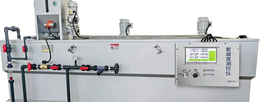
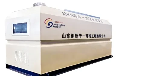
Integrated MBR equipment.
Biological treatment and membrane separation in one packaged plant — compact, reuse-ready and assembled as a complete unit for site connection and commissioning.
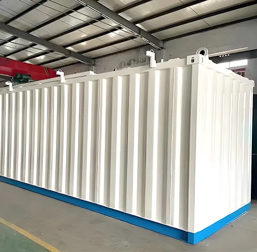
What it is
A membrane bioreactor (MBR) combines biological treatment with membrane separation. The biology removes organic matter and nitrogen; the membrane retains solids and pathogens that would otherwise carry over into the effluent. The result is a compact plant that produces a consistently high effluent quality, suitable for discharge or for reuse.
The process
- 1Biological reaction — bacteria remove organic matter and nitrogen in the aeration basin.
- 2Membrane separation — mixed liquor is drawn through membrane modules; solids and pathogens are retained.
- 3Permeate — clarified, low-turbidity water leaves the membrane.
- 4Disinfection and reuse — final pathogen reduction before discharge, irrigation or flushing.
The exact configuration — membrane type, aeration and tank volumes — is fixed during sizing, once the flow and the effluent target are known.
Advantages
Compact footprint
Biological treatment and separation share one tank volume, so the plant needs less space than a conventional train.
High effluent quality
The membrane acts as a physical barrier, retaining solids and pathogens.
Reuse-ready
Permeate is suitable for irrigation, landscaping and flushing where reuse is the objective.
Consistent performance
Performance is less sensitive to variations in solids settling than a conventional clarifier.
Lower sludge production
Operating at a higher solids concentration reduces the volume of surplus sludge to handle.
Specification parameters
Values are confirmed against the actual build for each project.
| Design flow | 0.5–10 m³/h (12–240 m³/day) per unit |
|---|---|
| Membrane type | [to be confirmed with factory] |
| Footprint | 3.5 × 1.5 × 2 m to 15 × 2.5 × 2.5 m, depending on capacity |
| Effluent quality | [to be confirmed with factory] |
| Power supply | [to be confirmed with factory] |
| Control mode | [to be confirmed with factory] |
| Installation | [to be confirmed with factory] |
Model range
The standard CXMBR series covers 0.5–20 m³/h per unit. Larger flows are met by running several units in parallel or by a custom build.
| Model | Capacity (m³/h) | Dimensions L × W × H (mm) | Units | Weight (t) | Air demand (m³/min) |
|---|---|---|---|---|---|
| CXMBR-0.5 | 0.5 | 3000 × 1500 × 2000 | 1 | 1.5 | 0.15 |
| CXMBR-1 | 1 | 4000 × 1500 × 2000 | 1 | 1.7 | 0.3 |
| CXMBR-2 | 2 | 5000 × 2000 × 2000 | 1 | 2.5 | 0.6 |
| CXMBR-3 | 3 | 7000 × 2000 × 2500 | 1 | 3.5 | 0.9 |
| CXMBR-5 | 5 | 10000 × 2500 × 2500 | 1 | 4.5 | 1.5 |
| CXMBR-10 | 10 | 16000 × 2500 × 2500 | 1 | 8.4 | 3 |
| CXMBR-20 | 20 | 16000 × 2500 × 2500 | 2 | 16.8 | 6 |
Dimensions are reference outline dimensions and weights are approximate shipping weights. Both are confirmed against the actual build once the site conditions are known.
Applications
Municipal and community
villages, towns and housing developments with a defined service area.
Resorts and hotels
properties that need reliable treatment and reuse away from a central sewer.
Industrial
process and site wastewater where effluent quality or reuse matters.
Construction camps
temporary sites that need treatment now and relocation later.
Delivery
Units are assembled and tested before shipment, then shipped with export documentation. Loading arrangement and delivery schedule: [to be confirmed with factory].